Code Red Consultants
  •  

Most newly constructed multi-story buildings are designed with elevators to provide both movement and accessibility benefits within a facility. With that said, elevators and their associated hoistways can present significant fire and smoke spread challenges if not properly protected. For this reason, current model building codes require hoistways to be fire resistance rated unless an exception is met. A 1- or 2-hour fire resistance rating is required which is dependent on the number of floors connected by the shaft (1-hour if less than 4-stories; 2-hour if 4-stories or more), and the fire resistance rating of the floor assemblies within the building.

Standard elevator hoistway doors are constructed to be fire rated for compliance with the criteria noted above; however, are typically not designed to limit floor-to-floor smoke spread. As such, building codes have supplemental requirements for hoistway opening protection at or around the elevator car doors. In fully sprinklered buildings, this applies to elevator hoistways connecting more than 3-stories and having either of the following conditions apply (780 CMR 3006.2):

  • The building contains one of the following special Institutional occupancies: Group I-1 Condition 2, Group I-2, or Group I-3.
  • The building is a high-rise and the hoistway is more than 75-feet in height as measured from the lowest floor to the highest floor of the floors served by the hoistway.

If triggered by the above, the following elevator hoistway opening protection options are available (780 CMR 3006.3):

  • An enclosed elevator lobby consisting of smoke partitions is provided at each floor (except at the level(s) of exit discharge) to separate the hoistway from the floor. Lobby doors are required to be self-or-automatic closing, positive latching, and listed as smoke and draft control assemblies per UL 1784. Duct and air transfer openings penetrating a lobby require smoke dampers unless an exception is met.
  • Provide additional doors at each elevator hoistway car door opening at each floor (except at the level(s) of exit discharge) that are operable from the car side without a key, tool, or special effort. The doors are also required to be listed as smoke and draft control assemblies per UL 1784 when tested without an artificial bottom seal. It is common to see elevator smoke curtains used for this application.
  • Pressurize the hoistway with a smoke control system in accordance with 780 CMR 909.21.

Note: Specialty elevators such as fire service access and occupant evacuation elevators have separate and more stringent requirements that must be evaluated separately.

Background

Fire alarm systems are a critical building life safety component that require ongoing inspection and maintenance to ensure they operate properly during a fire. When an existing building undergoes renovation, and impairments may occur to passive and active fire protection systems, it is critical that systems that remain online are working properly, as the fire hazard in the building increases due to the presence of construction.  Occasionally, however, existing fire protection systems in buildings under renovation are found to be lacking required maintenance or simply not functioning.

The Massachusetts Comprehensive Fire Safety Code (527 CMR 1.00) requires inspection, testing and maintenance of fire alarm systems be performed in accordance with the provisions of NFPA 72, National Fire Alarm and Signaling Code. Inspection, testing, and maintenance requirements in NFPA 72 are contained in Chapter 14.

Inspection Requirements

As stated previously, the purpose of inspection, testing and maintenance is to ensure the fire alarm system is functioning properly.  This includes both visual inspection and functional testing.  Both are required, because some physical impairments, such as the fire alarm panel being blocked by storage, a dust cover being left on a smoke detector, or a heat detector not mounted to the ceiling, may render the device or the system itself inoperable.

Visual inspection ensures devices have not been physically damaged, covered, obscured, or even removed and bypassed.  Functional testing ensures devices are performing within their listed parameters, for example a smoke detector triggering an alarm signal after being tested with canned smoke.  The number of functional tests for different components are too numerous to list here but are described along with their prescribed test frequency in NFPA 72, Table 14.4.3.2.

Fire alarm systems can be integrated with many other life safety systems, such the sprinkler system, smoke control systems, other specialized extinguishing systems, generators, and elevators. Integrated systems may be supervised by the alarm system and may generate fire alarm-initiating signals and/or receive output signals from the alarm panel.  Where other systems are installed and maintained under a separate NFPA standard, their inspection and testing is performed under their respective standard.  These systems may require separately licensed, specialized technicians to safely operate or reset controls that the fire alarm company cannot perform.  Signal initiation from an integrated system, which does not have to include actual system activation, or receipt of an output signal, are the extent of the fire alarm test requirements.

The testing of fire alarm components should include activation of notification appliances – audible and visual alarms. In office buildings, this testing may preferably be conducted off-hours. In a residential building, it is likely that the testing takes place during the day. Newer fire alarm systems may include automatic self-test modes; these self-tests should be verified.

Who May Inspect

Responsibility for periodic inspection, testing and maintenance falls upon the building owner or their designated representative.  This is required both by 527 CMR 1.00 (Section 10.2) and NFPA 72 (Section 14.2.3).  In Massachusetts, a person testing a fire alarm system (also referred to as a fire warning system) must be licensed by the Board of State Examiners of Electricians, in accordance with 237 CMR.

Recordkeeping

A building owner may be asked at any time to present documentation of up-to-date inspection, testing, and maintenance any time by Fire Department officials, and those records are required to be maintained for at least one year.  This request can be initiated for many reasons, including during a regularly scheduled inspection, as part of a permit application, or in response to a complaint.  Any records that are maintained should be organized, such as in a binder organized by system and date; or can be electronically maintained. Regardless of what system is utilized, the inspection reports should identify any discrepancies noted during the inspection as well as remedial action that was taken.

If you have any questions regarding fire alarm system maintenance or fire alarms during renovation projects, please contact our office at info@crcfire.com or 617-500-7633.


Projects in occupied buildings in Boston undergoing renovation have a renewed focus on the continued maintenance of Fire Protection and Life Safety Systems in these buildings. This Insight will help to explain the different systems that have come under review, code requirements for maintenance, and how you can best plan in advance.

What is considered a Fire Protection or Life Safety (FPLS) System?

Of the many systems that are present in a typical urban building, the following are critical for ensuring the safety of occupants in the event of a fire:

  • Fire Alarm Systems
  • Fire Protection Systems (sprinklers and standpipe systems)
  • Fire Protection Water Supply (fire pumps)
  • Smoke Control Systems
  • Emergency Power Systems (generators)

Each of these systems is a complex combination of components working together to protect the building occupants, and it is important that the systems work as intended every time they are called upon. Since the nature of these systems is that they should only activate in the event of an emergency, a routine and regular testing schedule needs to be implemented. This is critical during construction in an occupied building, as systems may be impaired, and the risk of fires is increased due to the presence of construction.

What are the requirements?

The Massachusetts Comprehensive Fire Safety Code (527 CMR 1.00) requires owners, operators, or occupants to to keep records of all maintenance, inspections, and testing of fire protection systems, fire alarm systems, smoke control systems, and emergency power equipment until their useful life has been served, as required by law, or as required by the AHJ (Sections 10.2.5 and 10.2.6).

Several codes and standards outline the specific inspection and testing requirements for FPLS Systems. The relevant standard for water-based systems is NFPA 25, Standard for the Inspection, Testing, and Maintenance of Water-Based Fire Protection Systems. Fire alarm system inspections and testing must comply with Chapter 14 of NFPA 72, National Fire Alarm and Signaling Code, while smoke control system testing requirements are in Chapter 8 of NFPA 92: Standard for Smoke Control Systems. Lastly, generator tests are described in NFPA 110, Standard for Emergency and Standby Power Systems. 

A record of your systems’ maintenance may need to be produced at the building’s quarterly or annual city inspections, when applying for an alteration permit, when getting TCO or occupancy for a completed renovation, or simply if an AHJ shows up for any reason and request said reports.

This Insight is the first in a new mini-series. You can expect to see the specific maintenance and testing requirements for each type of system discussed in more depth throughout the series. Using the links below you can find prior Insights for the following systems:

  1. Standpipe – (August 2016) https://coderedconsultants.com/insights/you-will-not-get-your-ti-certificate-of-occupancy-in-boston-if-you-are-missing-this-test/
  2. Smoke control – (March 2017) https://coderedconsultants.com/insights/requirements-for-existing-building-smoke-control-retesting/
  3. Fire pump – (June 2021) https://coderedconsultants.com/insights/fire-pump-flow-test-reports/

If you have questions on the inspection, testing, or maintenance requirements for your fire protection or life safety system, please contact us at info@crcfire.com.

*images by Vecteezy


Often during the design process the benefits of utilizing a fire wall arise, with “what will this get me?” coming into question.  The use of fire walls as part of a building’s code strategy can allow for the realization of substantial benefits, but users also must be aware of what a fire wall installation will not get them.

A fire wall is a “A fire-resistance-rated wall having protected openings, which restricts the spread of fire and extends continuously from the foundation to or through the roof, with sufficient structural stability under fire conditions to allow collapse of construction on either side without collapse of the wall” (780 CMR 202).

The two main benefits of a fire wall for consideration are:

  1. Height and Area: The height and area of each building separated by a fire wall is evaluated separately. This allows for taller buildings and/or larger footprint areas since the heights and areas of adjacent structure is evaluated between fire walls, as opposed to the aggregate area of abutting structures.
  2. Construction Type: Buildings separated by a fire wall are permitted to consists of different construction types. In other words, on one side a building could be combustible, wood framed construction and on the other side could consist of noncombustible steel construction as long as height and area limitations are not exceeded for each side independently.

Depending on local code amendments, fire walls can also influence factors such as evacuation zoning, fire protection system scoping, etc.

To assure that fire walls provide sufficient protection to prevent fire spread or compromise to the structural integrity of buildings separated, there are a number of requirements that need to be met to assure that these assemblies are constructed to meet this objective. Stay tuned for the next insight as part of this fire wall series outlining how fire walls are constructed.

If you have any questions regarding fire walls on your project, please contact our office at info@crcfire.com or 617-500-7633.


Energy Storage Systems (ESS) are quickly gaining popularity in both commercial and residential applications, and the newness of the technology combined with some high-profile historical fires have led Authorities Having Jurisdiction (AHJ’s) to be somewhat wary.

ESS are essentially a large battery system of single cells (usually Lithium Ion) connected together, often used to store energy from alternative sources (solar, wind, etc.), or to store utility power for use during peak demand times.  The battery technology is constantly evolving, and the design and size of ESS can vary a great deal, making them challenging for an AHJ to evaluate.

The potential risks of an ESS fire can be considerable.  Battery fires can be difficult to extinguish and can produce explosive and environmentally hazardous byproducts.  These unique factors led to the development of a dedicated Standard to help the industry properly protect against the dynamic challenges posed by this new equipment and technology.

While not yet formally adopted in most jurisdictions, NFPA Standard 855, Standard for the Installation of Energy Storage Systems dictates requirements to designers and reviewers on many aspects of an ESS installation, including topics such as:

  • Size limits
  • Location and separation from adjacent structures
  • Physical protection and security
  • Fire Department access, water supply and suppression strategies
  • Hazard Mitigation Analysis (HMA) of potential failure modes
  • Explosion prevention and control
  • Emergency preparedness and response planning
  • Commissioning, Operation and Maintenance

An NFPA 855 review, completed by either the design team, a third-party, or the AHJ, encourages a methodical and thorough evaluation and can go a long way in ensuring a baseline level of safety for ESS installations.  If you have questions regarding how to apply these requirements to your project, please contact us at info@crcfire.com.

A wet pipe sprinkler riser is required to have specific components to perform as required per NFPA 13, Standard for the Installation of Sprinkler Systems. A wet pipe system riser typically contains either an alarm check valve assembly or a “shotgun” riser assembly which are used to maintain system pressure and provide waterflow notification. Both styles of riser provide their own benefits and disadvantages that should be considered when designing a wet pipe system.

Historically, Alarm Check Valves provided notification of waterflow before electrical waterflow alarms were used. These valves controlled the flow of water to a bell called a water motor gong, which is discussed further below. An Alarm Check Valve consists of multiple components that make up the entire valve assembly. These components include the following:

  • Check valve clapper – The clapper is the component that maintains water pressure on the system side of the alarm check valve assembly. Once a pressure drop on the system side occurs from either an opened sprinkler head or other form of waterflow, the alarm check valve clapper will open and provide the system with water from the water supply. This clapper also controls the flow of water to the waterflow alarm.
  • Pressure Gauges – Pressure gauges are devices that indicate the current pressure with the sprinkler system. On an alarm check valve assembly, there is usually a pressure gauge on the system side and one on the water supply side of the clapper. Typically, the pressure on the system side of the clapper is greater than the water supply side of the clapper.
  • Pressure Switch – A pressure switch is a type of waterflow alarm, which simply detects the force of water pushing against it. When the clapper opens inside the Alarm Check Valve, water is allowed to push up against the pressure switch, sending an alarm signal to the building’s fire alarm panel. The fire alarm will then notify occupants and transmit a signal to a central station monitoring service or directly to the fire department.
  • Water Motor Gong – A water motor gong is a mechanical bell – driven by water – that provides localized notification when water is actively flowing through the system. Water motor gongs can be seen on older buildings as a large, flattened dome, cast iron bell mounted on an exterior wall. Gongs will always have a drain immediately beneath them. When the Alarm Check Valve clapper opens during a water flow, a pipe is uncovered which allows water to flow to the gong. This water strikes a water wheel inside the gong, spinning the wheel and driving the hammer inside the gong. The spent water then runs freely out the drain to the exterior of the building. Water motor gongs are seen less in newer system installations as they have been replaced by electric-powered bells.
  • Retard Chamber – A retard chamber is used to create a mechanical delay to mitigate false alarms caused by water surges in a system. The retard chamber is a small tank (typically 1 gallon) located between the Alarm Check Valve and the pressure switch and water motor gong piping. The tank must first fill with water before traveling through the trim piping and activating the notification devices, causing a mechanical time delay. This delay helps mitigate false alarms caused by water surges in the system by preventing immediate activation of the notification devices.

One benefit of an Alarm Check Valve is that it provides mechanical notification through the associated trim components, such as the water motor gong. Electrical power is not required to initiate an audible alarm signal, water pressure alone drives the alarm. This provides an alternate, backup alarm signal beyond the required fire alarm components. The necessity of a water motor gong is typically enforced by the AHJ as they are not required on wet pipe systems by NFPA 13. If a water motor gong is required by the AHJ to be installed for a system, an Alarm Check Valve assembly should be specified for the project.

A shotgun riser assembly has a similar function to an Alarm Check Valve – it maintains system pressure and initiates alarm signals. The main difference in these two styles is that a shotgun riser assembly does not contain the associated trim components that are provided on an alarm check valve assembly, such as a pressure switch, retard chamber, or water motor gong. The shotgun assembly is provided with a simple check valve (which is often the system’s backflow preventer and not a separate check valve), pressure gauge, and a waterflow alarm device. The waterflow alarm is typically a paddle-type switch, rather than a pressure switch. The paddle-type alarm has a plastic arm located inside the pipe. When water flows, it moves the paddle, activating an electrical switch mounted on the pipe. This sends an alarm signal to the building’s fire alarm system, notifying a central station monitoring company or the fire department. Shotgun riser assemblies are far simpler than an Alarm Check Valve, and do not require the associated trim components which usually helps to reduce installation costs.

It is important to understand the differences in the types of risers when designing and specifying the components for a new wet pipe system. Each type has benefits and downsides that should be considered on a project specific basis. If you have any questions on which type of riser assembly would be best fit for your project, please contact our office at info@crcfire.com.


Public subway systems and light rail stations serving urban communities contain a unique occupancy due to the nature of transient ridership throughout their operation. The National Fire Protection Association (NFPA) recognizes the distinct characteristics of rail stations and has developed NFPA 130, Standard for Fixed Guideway Transit and Passenger Rail Systems, for the protection of such unique occupancies, which has been adopted in Massachusetts through 780 CMR The Massachusetts State Building Code.

Given the special challenges associated with the occupancy of rail stations, NFPA 130 evaluates the means of egress system using performance-based evaluations.  These evaluations are based on the performance of the station’s egress features and use timed 4- and 6-minute tests.  This approach differs from the normal method of evaluation in the building code for most other occupancies which uses occupant load factors and egress width factors.

A key component to these performance-based calculations is the determination of the anticipated occupant load (i.e. ridership) that will need to be evacuated from the station and/or platform, which is determined in a manner that accounts for numerous variables specific to the facility.  Another aspect of rail stations that differs from most other building types is that, often, station occupant loads are expected to grow over time to account for factors such as population growth, ridership increase, surrounding developments, etc.  This occupant load plasticity, in contrast to other occupancy types, necessitates the periodic re-evaluation of the means of egress of stations.

Apart from normal population growth, a station’s occupant load may be significantly impacted by projects and development in the surrounding area. Where this is the case, the previous egress system within the neighboring rail station(s), that may have once been adequate to support the original station’s ridership, may be rendered inadequate to support the resulting occupant load in the future. Such projects that may alter the occupant load and necessitate a re-evaluation of the station’s means of egress can include the following:

  • Projects located within the air-rights of an existing station;
  • Projects that are part of Transit Oriented Developments that is focused on the ease of access to a nearby public transportation; or
  • Projects involving a large new assembly facility such as a stadium or conference center located along a transit line.

Building or renovating near a transit station? Make sure thought is given to the effect this can have on ridership, station occupant load, and means of egress.

If you have questions regarding how to apply these requirements to your project, please contact us at info@crcfire.com.

Entrance canopies found at the main door of many buildings are considered “exterior projections” by NFPA 13 Standard for the Installation of Sprinkler Systems and may require sprinkler protection when exceeding 4 feet in width and/or where storage is located below the canopy. The 2013 edition of NFPA 13 currently applicable in Massachusetts contains two exceptions applicable to entrance canopies exceeding 4 feet in width, which are outlined below.  It should be noted that, where storage of combustible materials is located below canopies, sprinkler protection is required when such canopies exceed 2 feet in width regardless of whether one of these exceptions is otherwise applicable (NFPA 13 §8.15.7.4).

The first exception states that sprinklers can be omitted where the canopy is constructed with materials that are noncombustible, limited-combustible, or fire retardant-treated wood (NFPA 13 §8.15.7.2). These types of materials are specifically defined terms in NFPA 13 and NFPA 703 Standard for Fire Retardant-Treated Wood and Fire-Retardant Coatings for Building Materials (2012 edition referenced by NFPA 13-2013), and these definitions are reproduced below for reference. Note that this exception requires that the entire canopy assembly meet these construction requirements, not just the exposed surface.

The second exception states that sprinklers can be omitted from canopies of combustible construction where the exposed finish material is noncombustible, limited-combustible, or fire retardant-treated wood (NFPA 13 §8.15.7.3). To meet this exception, however, the concealed spaces within the combustible canopy must also meet one of the following alternative options:

  • Be provided with sprinkler protection within the combustible concealed space (NFPA §8.15.7.3);
  • Be filled entirely with noncombustible insulation (NFPA 13 §8.15.7.3(1));
  • Meet specific construction requirements to limit enclosed joist spaces to 160 cubic feet or less in volume in accordance with NFPA 13 §8.15.7.3(2); or,
  • Be located over canopy areas not exceeding 55 square feet (NFPA 13 §8.15.7.3(3)).

Entrance canopies exceeding 4 feet in width are only permitted to be unsprinklered if they meet one of the exceptions above.  For such canopies without sprinkler protection, storage of combustible materials below the canopy is not permitted.

Referenced Definitions:

Noncombustible Material – A material that, in the form in which it is used and under the conditions anticipated, will not ignite, burn, support combustion, or release flammable vapors, when subjected to fire or heat; materials that are reported as passing ASTM E 136, Standard Test Method for Behavior of Materials in a Vertical Tube Furnace at 750°C, shall be considered noncombustible materials. (Reference NFPA 13 §3.3.17)

Limited-Combustible Material – Refers to a building construction material not complying with the definition of noncombustible material that, in the form in which it is used, has a potential heat value not exceeding 3500 Btu/lb (8141 kJ/kg), where tested in accordance with NFPA 259 Standard Test Method for Potential Heat of Building Materials, and includes either of the following: (1) materials having a structural base of noncombustible material, with a surfacing not exceeding a thickness of 1⁄8 in. (3.2 mm) that has a flame spread index not greater than 50; or (2) materials, in the form and thickness used, having neither a flame spread index greater than 25 nor evidence of continued progressive combustion, and of such composition that surfaces that would be exposed by cutting through the material on any plane would have neither a flame spread index greater than 25 nor evidence of continued progressive combustion, when tested in accordance with ASTM E 84, Standard Test Method of Surface Burning Characteristics of Building Materials, or ANSI/UL 723, Standard Test Method of Surface Burning Characteristics of Building Materials. (Reference NFPA 13 §3.3.16)

Fire retardant-treated wood – A wood product impregnated with chemical by a pressure process or other means during manufacture, which is tested in accordance with ASTME E 84 or ANSI/UL 723, has a listed flame spread index of 25 or less, and shows no evidence of significant progressive combustible when the test is continued for an additional 20-minute period; nor does the flame front progress more than 10.5 feet beyond the centerline of the burners at any time during the test. (Reference NFPA 703 §3.3.2).

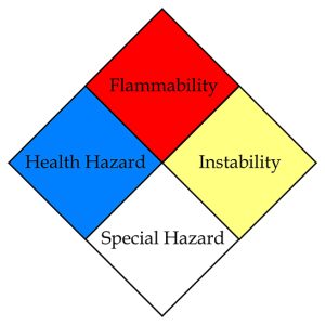
NFPA 704 Standard System for the Identification of the Hazards of Materials for Emergency Response is intended to standardize basic hazardous material signage into a simple, easily understood, and recognizable system.  Commonly referred to as “NFPA 704 diamonds”, these signs communicate four hazard categories: health hazard (blue), flammability (red), instability (yellow), and special hazard (white).

The degree of hazard for health, flammability, and instability hazards is on a scale of 0 – 4, with 4 assigned to materials that are the most hazardous, and 0 to materials that are the least hazardous. Recognized special hazards are represented by unique symbols in the special hazard quadrant and address water reactive materials (“W” with a horizontal line through it), oxidizers (“OX”), and simple asphyxiant gases (“SA”).

There may also be additional jurisdiction requirements for NFPA 704, so it is important to work closely with the local Fire Department in developing a coordinated and consistent signage package.  As an example, for new and existing laboratories, the Boston Fire Prevention Code specifies a slightly modified version of the NFPA 704 Diamond including a “G” designation for categories where hazardous compressed gases are included.

Detailed information and definitions pertaining to each of the hazard rankings is provided in NFPA 704 including primarily NFPA 704 Table 5.2 (health hazards), Table 6.2 (flammability hazards), and Table 7.2 (instability hazards).  However, the simple numerical system on the NFPA 704 diamonds allows Emergency Responders to quickly identify the relative hazards of a given material or space, and the potential severity thereof, prior to entering the space.  Understanding the hazards present helps inform the safest course of action to take during an emergency event.

Required locations of signage can be found in 527 CMR 1.00 Massachusetts Comprehensive Fire Safety Code, NFPA 704, as well as based on local jurisdiction requirements.  Refer to the Code Red Consultants blog post, Laboratory Emergency Signage, for more information on the types of laboratory signage.

If there is more than one chemical present in a specific area, or the building, there are three methods to indicate the hazard ratings applicable to the space:

  • Composite Method – If multiple chemicals are present, a single sign can be used to represent the maximum rating contributed by a material in each category. If there are special hazards, those would be listed as well on the sign.
  • Individual Method – If only a few chemicals are present, signs for each of the individual chemicals can be posted with the chemical name written on the sign.
  • Composite-Individual Combined Method – This method would employ the composite method for some spaces and the individual method for other spaces, depending on the number of chemicals within each area.

If you have any questions or would like assistance with fire and life safety code compliance relative to laboratories, please do not hesitate to contact us at info@crcfire.com.


New FPPM Requirements in Boston – Updated February 2, 2023

Given the increasing number and severity of construction fire incidents in Boston, the Boston Fire Department (BFD) has established a new training requirement for Fire Prevention Program Managers (FPPMs) on construction sites in the city. Effective January 1, 2023, all FPPMs and Alternate FPPMs serving Boston construction sites are minimally required to have taken the National Fire Protection Association’s (NFPA) online FPPM Training prior to assuming the FPPM or AFPPM role.

This new expectation is driven by recent frustrations experienced by BFD, where many project FPPMs have voiced or demonstrated that they were not aware of the responsibilities of the position. An FPPM is not just a “check in the box,” but is a crucially important part of fire and worker safety on a jobsite. Among the responsibilities are such elements as:

  • Overall responsibility for safeguarding life and property during construction, alteration, and demolition projects;
  • Authority to enforce the NFPA 241 Plan – including speaking with the authority of the GC or the Owner;
  • Knowledge of fire protection codes and standards, available fire protection systems, and fire inspection procedures;
  • Providing training to workers;
  • Supervising hot work permitting;
  • Coordinating impairments

Given these responsibilities, and that FPPMs on many projects in the city do not have the necessary backgrounds to be serving in the role, BFD has set this new training expectation for all FPPMs in the city.

The NFPA FPPM Training is available at the NFPA’s website, a link is provided at the end of this post. The online training program takes approximately five to six hours to complete. This training is currently the only program that is acceptable to BFD.

Separate from the FPPM training, there are new expectations associated with the Construction Fire Safety Plan contents. Specifically, the following must be included with each submission to BFD:

  1. The NFPA FPPM Certificate for the FPPM and any AFPPMs.
  2. For any project that includes a standpipe (new construction of a building with a standpipe, or a renovation, demolition, or tenant fitout in a building that has standpipes), BFD is additionally requiring an affidavit that an FPPM is assigned the project. The affidavit includes contact information for the FPPMs (primary and alternate) and the building owner, and must be signed by the licensed builder responsible for the project. This affidavit is available on BFD’s Fire Prevention Division’s website, a link to the affidavit is provided below.

These new expectations are intended to bolster the already robust construction fire safety requirements in the city. As the pace of construction and the complexity of the projects continues, well-trained FPPMs on projects will help to ensure that the NFPA 241 Plans are followed. This should result in a reduction in hazards that contribute to construction fires and accidents.

If you have questions about this new training requirement, please contact our office at 617-500-7633 or info@crcfire.com to speak with our construction fire safety team.

The link to the NFPA Fire Prevention Program Manager Training:

https://catalog.nfpa.org/Fire-Prevention-Program-Manager-Online-Training-Series-P21761.aspx

The link to the BFD NFPA 241 Affidavit:

https://www.boston.gov/sites/default/files/file/2023/01/NFPA%20241%20Affidavit_1.pdf